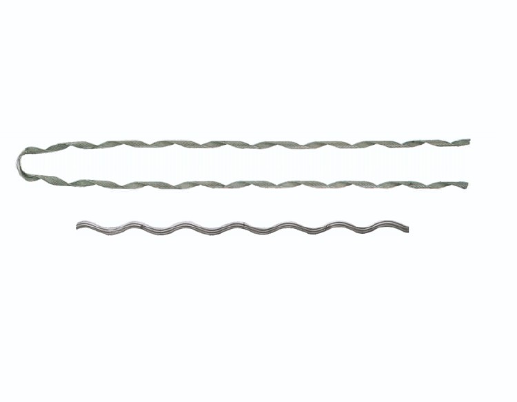
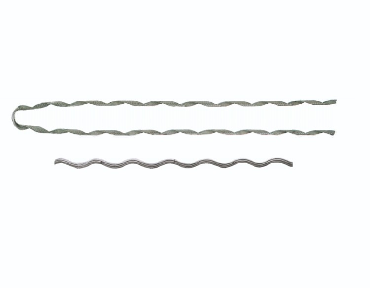
| Catalog No. | Conductor | Dimensions(mm) | Nominal Current | Weight(kg) | |||
| Main line | Branch line | A | B | H | |||
| FTY-95/15 | LGJ-95/15 | 13.61 | 3.6 | 11.4 | 1400 | 13 | 0.53 |
| FTY-95/20 | LGJ-95/20 | 13.87 | 3.6 | 11.4 | 1400 | 13 | 0.54 |
| FTY-120/20 | LGJ-120/20 | 15.07 | 3.6 | 12.5 | 1400 | 14 | 0.57 |
| FTY-120/25 | LGJ-120/25 | 15.74 | 3.6 | 13 | 1400 | 14 | 0.58 |
| FTY-150/20 | LGJ-150/20 | 16.67 | 3.6 | 14.7 | 1500 | 16 | 0.65 |
| FTY-150/25 | LGJ-150/25 | 17.1 | 3.6 | 14.2 | 1500 | 16 | 0.64 |
| FTY-150/35 | LGJ-150/35 | 17.5 | 3.6 | 14.5 | 1500 | 16 | 0.66 |
| FTY-185/25 | LGJ-185/25 | 18.9 | 4.6 | 15.7 | 1800 | 14 | 1.25 |
| FTY-185/30 | LGJ-185/30 | 18.88 | 4.6 | 15.7 | 1800 | 14 | 1.26 |
| FTY-185/45 | LGJ-185/45 | 19.6 | 4.6 | 16.3 | 1800 | 14 | 1.26 |
| FTY-240/30 | LGJ-240/30 | 21.6 | 4.6 | 17.9 | 1900 | 16 | 1.44 |
| FTY-240/40 | LGJ-240/40 | 21.66 | 4.6 | 17.9 | 1900 | 16 | 1.44 |
| FTY-240/55 | LGJ-240/55 | 22.4 | 4.6 | 18.6 | 1900 | 16 | 1.5 |
| FTY-300/20 | LGJ-300/20 | 23.43 | 6.3 | 19.4 | 2000 | 13 | 2.3 |
| FTY-300/25 | LGJ-300/25 | 23.76 | 6.3 | 19.7 | 2000 | 13 | 2.33 |
| FTY-300/40 | LGJ-300/40 | 23.94 | 6.3 | 19.9 | 2000 | 13 | 2.34 |
| FTY-300/50 | LGJ-300/50 | 24.26 | 6.3 | 20.1 | 2000 | 13 | 2.34 |
| FTY-400/25 | LGJ-400/25 | 26.64 | 6.3 | 22.1 | 2200 | 14 | 2.8 |
| FTY-400/35 | LGJ-400/35 | 26.82 | 6.3 | 22.3 | 2200 | 14 | 2.8 |
| FTY-400/50 | LGJ-400/50 | 27.63 | 6.3 | 23 | 2200 | 14 | 2.8 |
| FTY-400/65 | LGJ-400/65 | 28 | 6.3 | 23.2 | 2200 | 14 | 2.83 |
| FTY-500/35 | LGJ-500/35 | 30 | 6.3 | 24.9 | 2500 | 16 | 3.48 |
| FTY-500/45 | LGJ-500/45 | 30 | 6.3 | 24.9 | 2500 | 16 | 3.48 |
| FTY-500/65 | LGJ-500/65 | 30.96 | 6.3 | 25.7 | 2500 | 16 | 3.5 |
| FTY-630/45 | LGJ-630/45 | 33.6 | 7.8 | 27.9 | 2500 | 15 | 5.32 |
| FTY-630/55 | LGJ-630/55 | 34.32 | 7.8 | 28.5 | 2500 | 15 | 5.4 |
| FTY-630/80 | LGJ-630/80 | 34.32 | 7.8 | 28.9 | 2500 | 15 | 5.4 |
1.A "dead-end" refers to the end of a transmission line where it does not continue onwards or connect to another line. It's typically where the line is physically secured to a pole or tower using dead-end insulators or hardware.
2.These components are designed to withstand the mechanical load of the line tension while electrically insulating the live conductor from the ground or support structure.
3.Dead-ends are crucial for maintaining the stability and integrity of power transmission lines, especially where the line changes direction or at the terminal point of the line. They ensure that the electrical path ends safely without causing any hazards or interruptions to the power supply.


