| stable design Cataiog No. | Suitable Conductor | Main dimensions(mm) | No of a group | Weight (kg) | ||
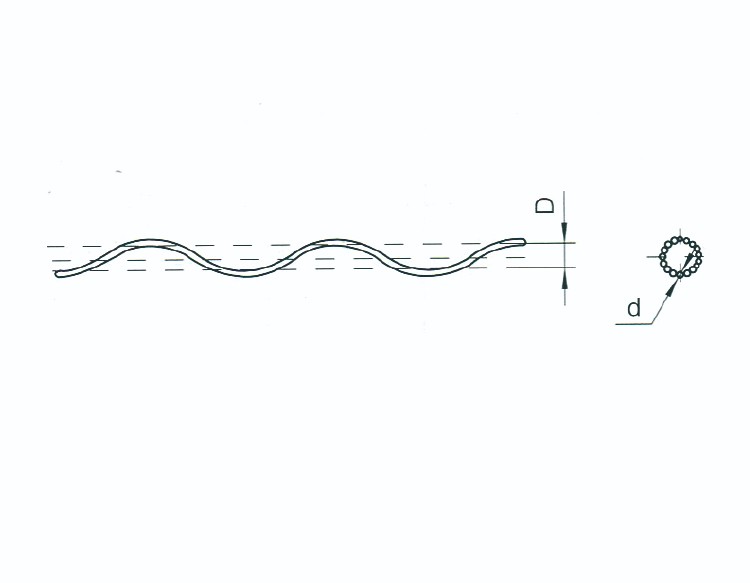
| D | d | L | ||||
| FYH-95/20 | JL/G1A-95/20 | 11.4 | 3.6 | 1400 | 13 | 0.55 |
| FYH-150/25 | JL/G1A-150/25 | 14.2 | 3.6 | 1500 | 16 | 0.7 |
| FYH-185/30 | JL/G1A-185/30 | 15.7 | 4.6 | 1800 | 14 | 1.3 |
| FYH-240/30 | JL/G1A-240/30 | 17.9 | 4.6 | 1900 | 16 | 1.5 |
| FYH-240/40 | JL/G1A-240/40 | 17.9 | 4.6 | 1900 | 16 | 1.5 |
| FYH-300/25 | JL/G1A-300/25 | 19.7 | 6.3 | 2000 | 13 | 2.4 |
| FYH-300/40 | JL/G1A-300/40 | 19.9 | 6.3 | 2000 | 13 | 2.4 |
| FYH-400/35 | JL/G1A-400/35 | 22.3 | 6.3 | 2200 | 14 | 2.8 |
| FYH-400/50 | JL/G1A-400/50 | 23 | 6.3 | 2200 | 14 | 2.8 |
| FYH-500/45 | JL/G1A-500/45 | 24.9 | 6.3 | 2500 | 16 | 3.5 |
| FYH-630/45 | JL/G1A-630/45 | 27.9 | 7.8 | 2500 | 15 | 5.4 |
| FYH-630/55 | JL/G1A-630/55 | 28.5 | 7.8 | 2500 | 15 | 5.4 |
| Cataiog No. | Suitable Conductor | Main dimensions(mm) | No of a group | Weight (kg) | ||
| D | d | L | ||||
| FYH-50BG | LBGJ-50-23AC | 7.7 | 3.6 | 1000 | 9 | 0.95 |
| FYH-80BG | JLB1A-80 | 9.6 | 3.6 | 1400 | 12 | 1.61 |
| FYH-100BG | LBGJ-100-20AC | 11 | 3.6 | 1400 | 12 | 1.92 |
| FYH-120BG | JLB1A-120 | 12 | 3.6 | 1400 | 14 | 1.72 |
| FYH-150BG | LBGJ-150-40AC | 13.2 | 3.6 | 1500 | 15 | 1.98 |
| FYH-185BG | LBGJ-185-20AC | 14.5 | 3.6 | 1500 | 16 | 2.1 |
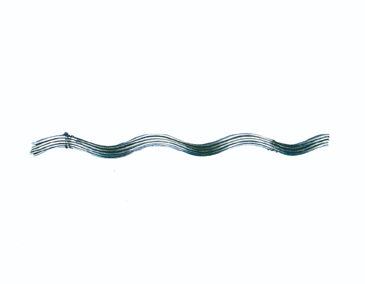
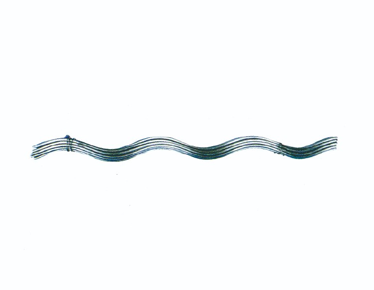
1. They safeguard the conductor against damage from bending, compression, abrasion, and flashover.
2.These rods are typically made of aluminum-clad steel wire or galvanized steel wire and can also be used to repair damaged conductors, restoring their mechanical strength and electrical conductivity.
3.The installation of these rods must be done carefully, ensuring that the lay direction of the armor rods matches the outer layer of the conductor to achieve maximum grip strength.


