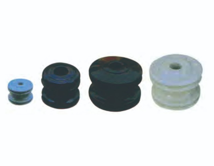
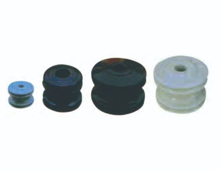
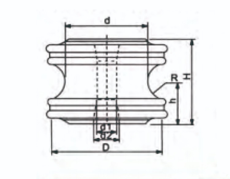
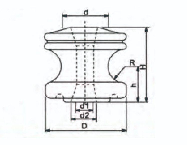
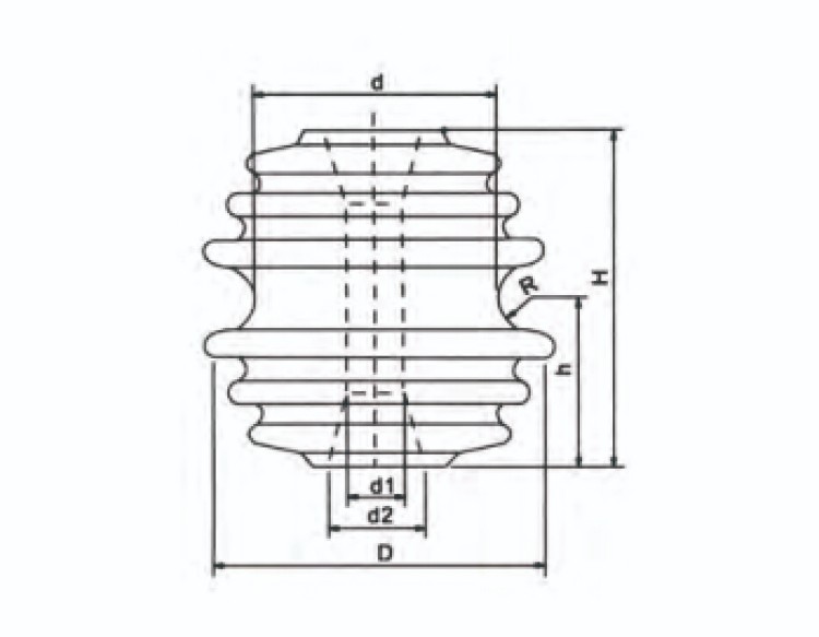
| Fig No | 1 | 2 | 1 | 1 | 3 | ||
| CLASS ANSI | 53-1 | 53-2 | 53-3 | 53-4 | 53-5 | ||
| Main Dimansions in( mm) | H | 54 | 76 | 81 | 76 | 105 | |
| h | 27 | 38 | 40.5 | 38 | 52.5 | ||
| D | 57 | 79 | 76 | 105 | 102 | ||
| d | 45 | 45 | 45 | 73 | 73 | ||
| d1 | 18 | 18 | 18 | 18 | 18 | ||
| d2 | 22 | 24 | 24 | 24 | 24 | ||
| R | 11 | 18 | 18 | 16 | 11 | ||
| Mechanical Failing Load ( KN ) | 8.9 | 13.3 | 13.3 | 20 | 26.7 | ||
| Leakage Distance ( mm ) | 20 | 25 | 25 | 25 | 35 | ||
| Flashover Voltage | Power Frequency | Dry (KV) | 8 | 12 | 12 | 12 | 18 |
| Wet (KV) | 10 | 15 | 15 | 15 | 25 | ||
| Weight (Kg) | 0.22 | 0.55 | 50.55 | 1.15 | 1.2 | ||
Here’s some information about them:
1.Material: They are often made of a fiberglass-reinforced resin rod core, polymer material weathersheds, and metal end fittings.
2.Application: These insulators are intended for use on overhead transmission lines for electric power systems, typically for voltages of 70 kV and above.
3.Types: There are different types of strain insulators such as pin, post, and dead-end insulators. Each type has its specific use cases. For example, pin insulators are preferred for new installations, including bare conductor, tree wire, and covered wire jumpers.
4.Installation: Care should be taken during installation. For instance, polyethylene insulators should not be overtightened as it can damage the neck of the insulator, leading to failure.


